Undulator information
This page contains information about the undulator, the component in the free-electron laser that generates the laser beam.
Overview
- An undulator is essentially a collection of dipole magnets assembled in rows, each pair alternating in polarity.
- These are put in the path of the electron beam to cause the beam to oscillate in a sinusoidal left-to-right motion.
- Due to this oscillation, the electrons in the electron beam radiate EM energy (the precise term is synchrotron radiation).
- This energy is in the form of light (or microwaves) which can be focused and absorbed elsewhere, just like a conventional laser.
Info
More information about the overall design can be found here on our research docs.
Photo gallery
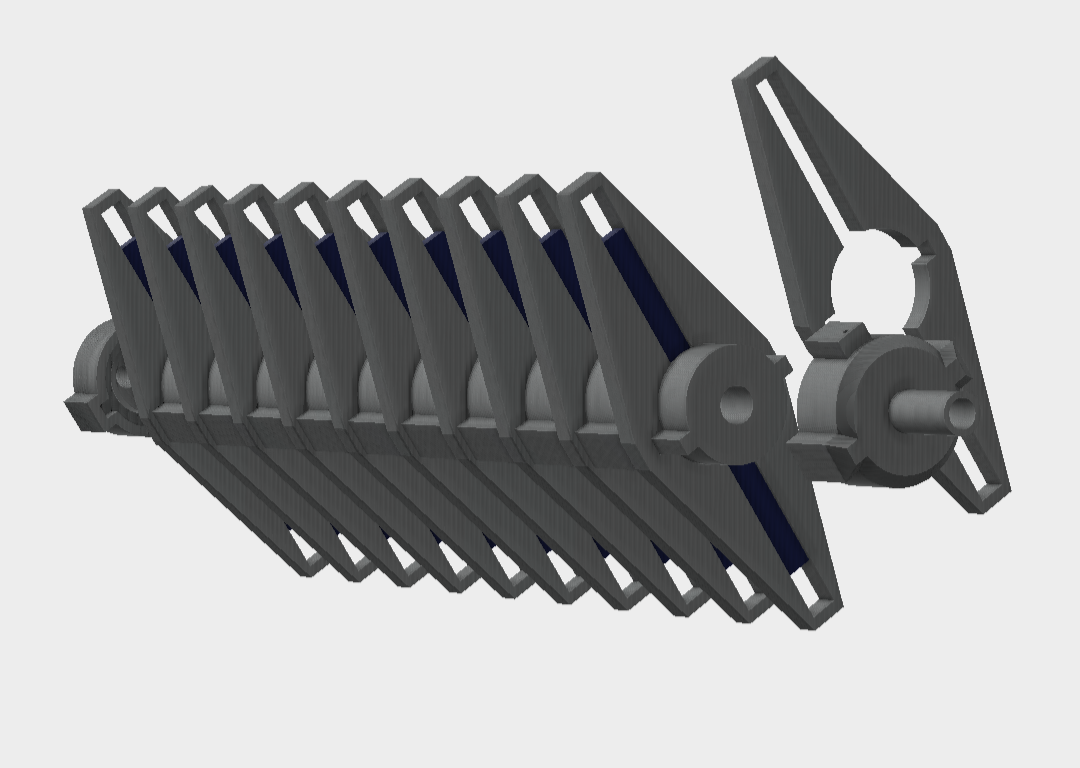
Preview of the undulator CAD model:
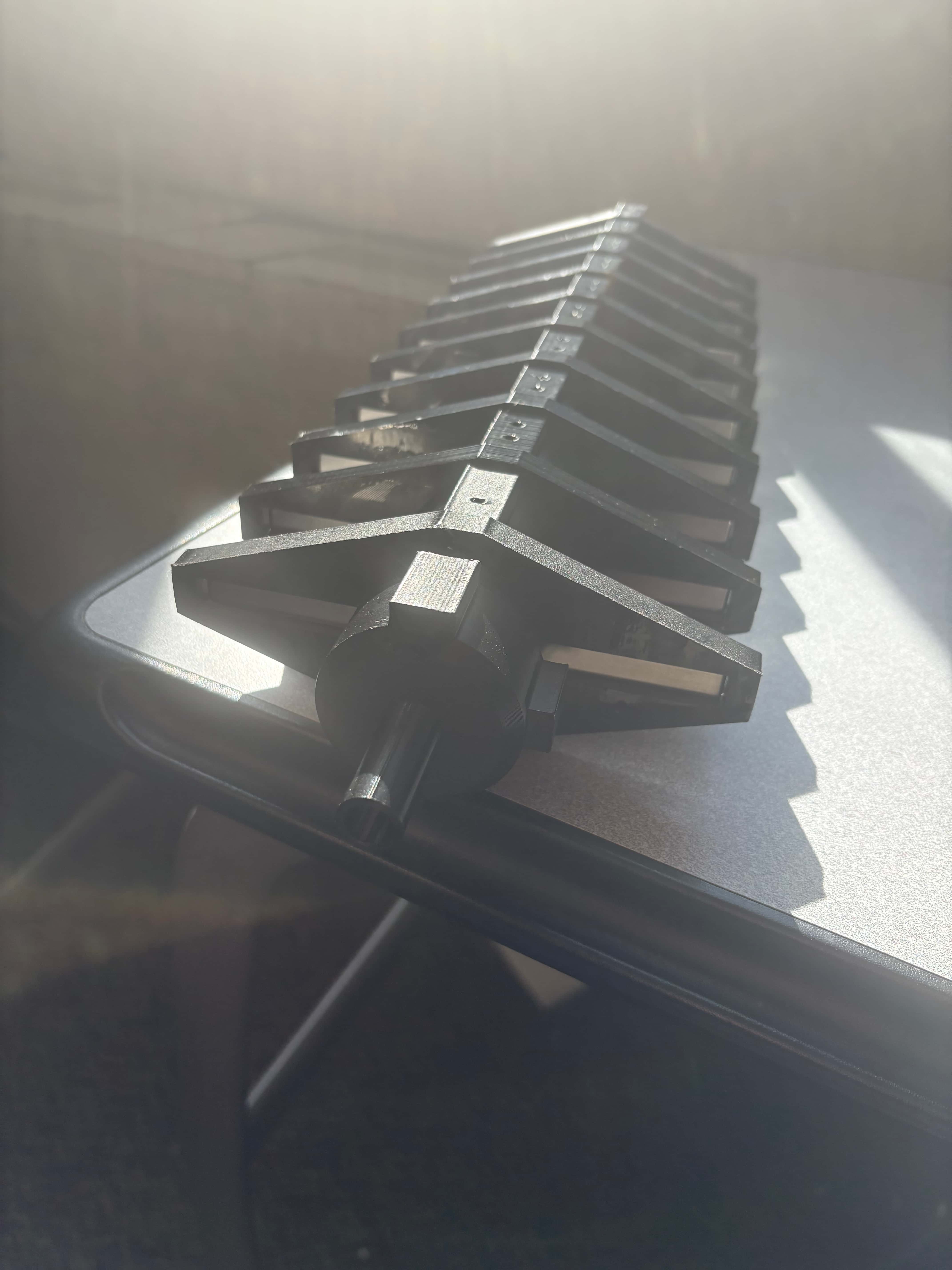
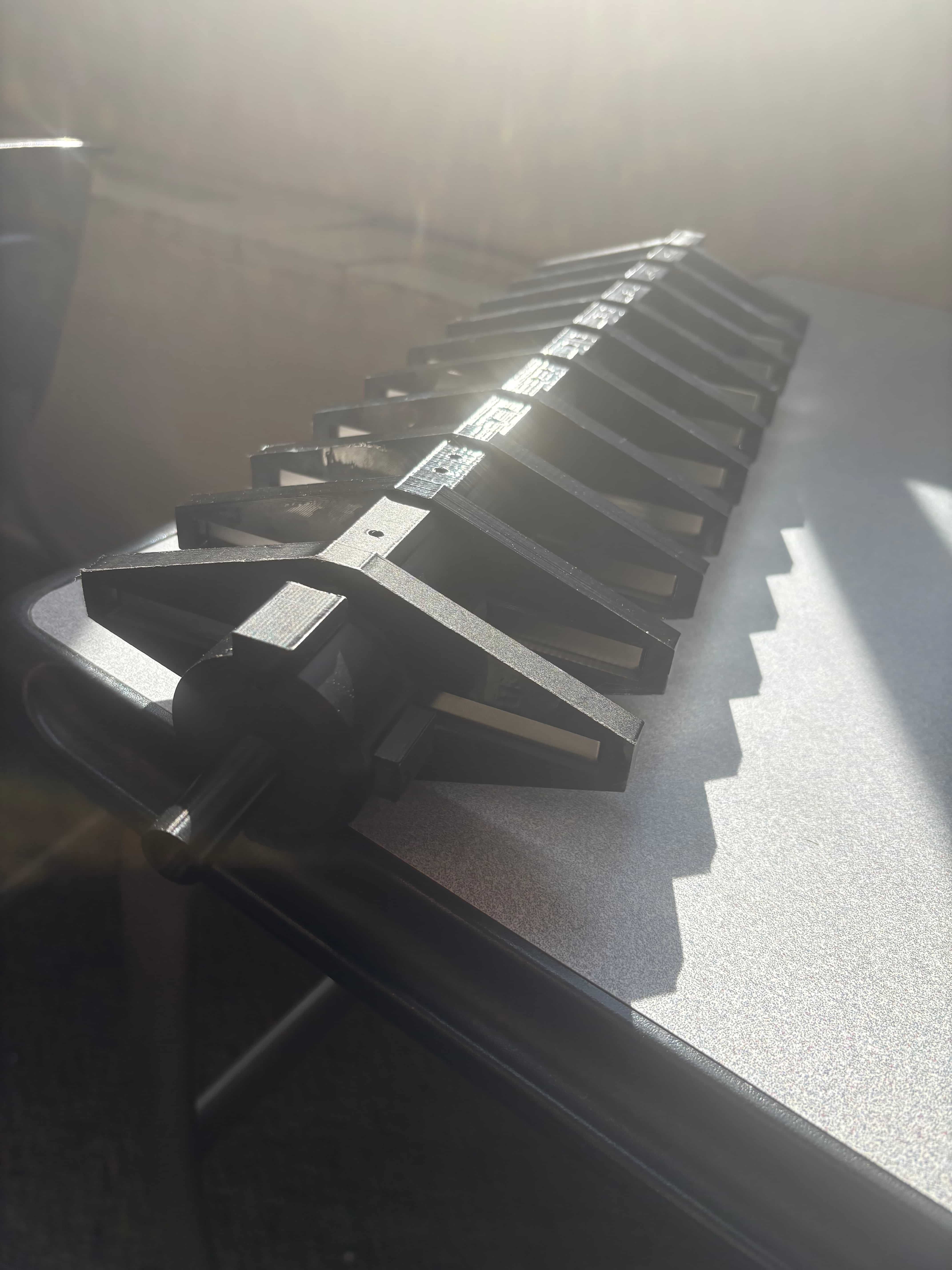
Constructed undulator photos:


Measurements and Details
- End cap internal measurements for the microwave reflectors: disk, 3cm outer radius, 1cm inner radius
- Inter-segment collar: 31 mm
- \(\lambda_u = \text{8 cm}\) -> undulator period aka double segment, [For a single magnetic period] (tessellated segment).
- Interlock distance 15.3522 -> check again odd sizing.
- \(w = \text{13 mm}\) -> electron beam shaft diameter
- \(L = \text{438.7 mm}\) -> total resonant cavity length.
- \(h = \text{175.4 mm}\) -> height of undulator
Future Plans for the Undulator Design
In the future, we plan to make a few improvements: - Create a magnet distance adjustor, instead of a static holder in the current design - Create a physical attachment point to the rest of the system - Make the spacing for the magnets adjustible (potentially) - Make it possible to change the number of magnets desired modularly
# Recommended reading
- Wikipedia article on undulators
- An educational video on undulators
- This guide on our research docs (be aware it is quite math-heavy)