Setup guide
Please ensure that you have all the required electrical components in the parts list before you begin building the circuits.
The raw circuit designs and simulations are available as .asc (LTSpice) files within the Elara laser repository's circuits subfolder. While LTSpice is freeware, it is unfortunately proprietary. If you do not have (or do not want to) install LTSpice, the diagrams can be converted into images and viewed using the ltspice2svg package, LTspice Tikz, or LT2circuiTikz.
Note
For the research that went into the design and our design rationale, please see the circuit research documentation.
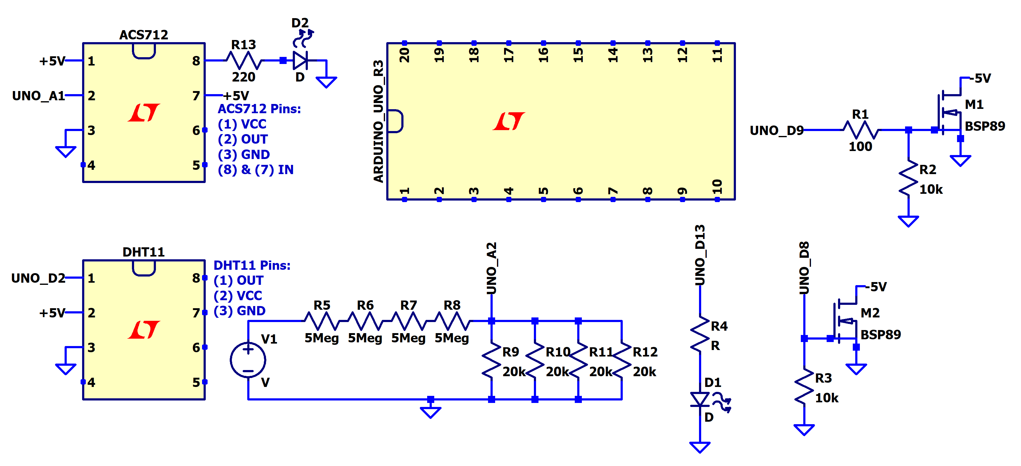
Full Sensor Schematic
All the circuits described in the following sections (with exception of the voltage sensor) are pictured below:
Current Sensor
Overview
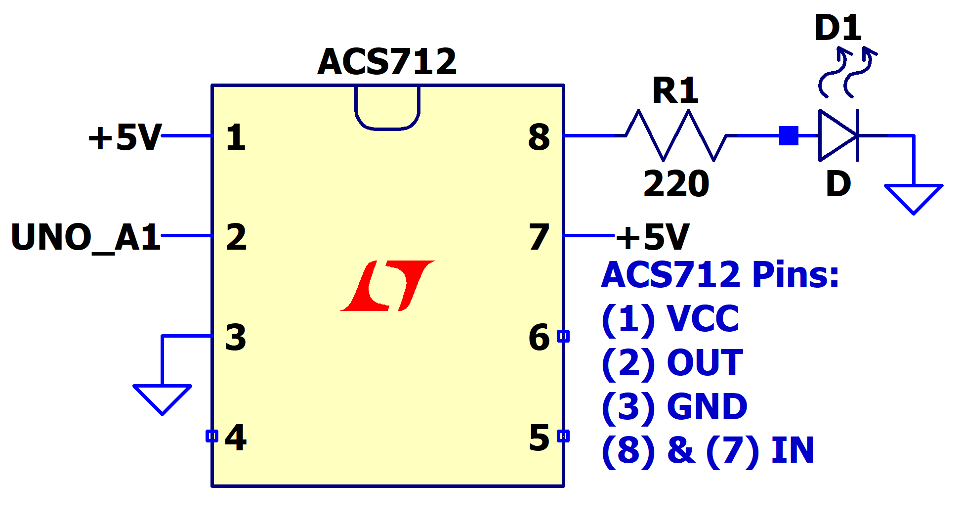
The ACS712 is a hall effect linear current sensor that can measure DC or AC current. There are 3 versions which measure up to 5A, 20A, or 30A current. The ACS712 operates at 5V and produces an output of 2.5V at 0A. The example circuit below measures the current at the resistor - LED node.
Components
- ACS712 30A Current Sensor
- 220 Ohm Resistor
- LED
Wiring
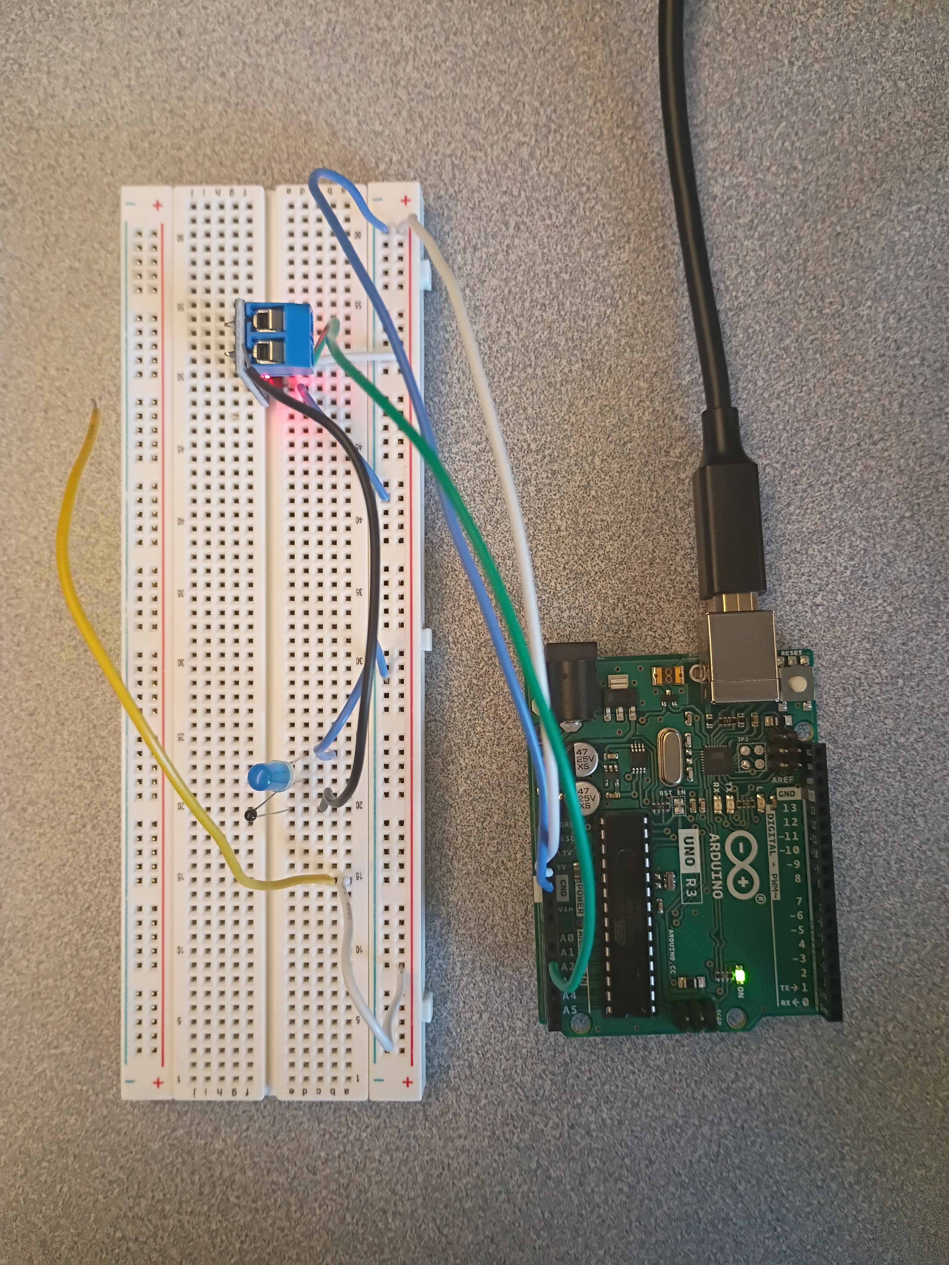
- Connect VCC to 5V on the Arduino
- Connect OUT to Arduino Pin A2
- Connect GND to Arduino GND
- Connect one channel of IN to a 220 resistor, then to LED and Arduino GND.
- Connect the other channel of IN to 5V on the Arduino
Schematic
Physical Circuit
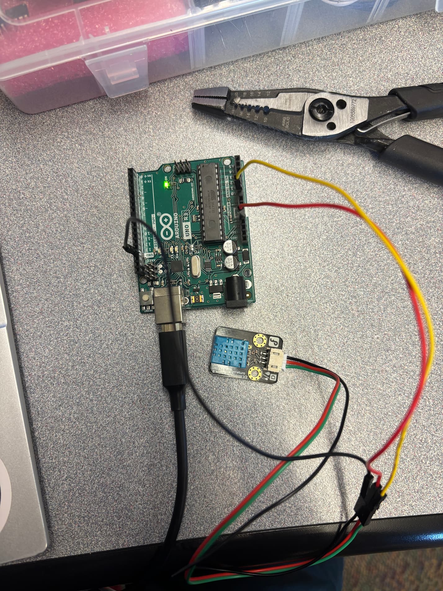
Temperature and Humidity Sensor
Overview
The DHT11 is a temperature and humidity sensor that measures 20-90% relative humidity and 0-50°C. It operates at 3.5 V to 5.5 V and has supported library for programming (Adafruit DHT Library). The DHT11 outputs a digital signal using single wire serial.
Useful reference: see this guide for more information setting up the sensor (the guide is for Raspberry Pi but should be easily adapted for arduino).
Components
- DHT11 Temperature and Humidity Sensor
Wiring
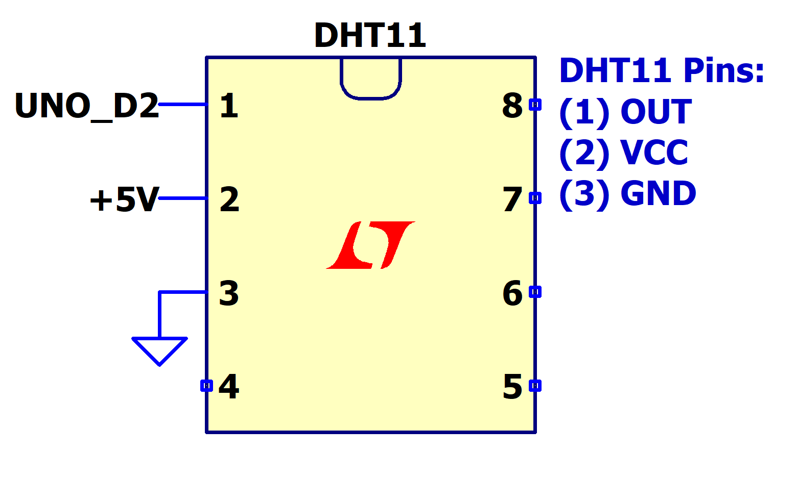
- Connect OUT to Pin D2 on the Arduino
- Connect VCC to Arduino Pin 5V
- Connect GND to Arduino GND
Schematic
Physical Circuit
Voltage Sensor
Overview
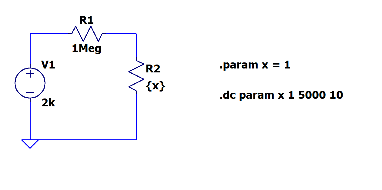
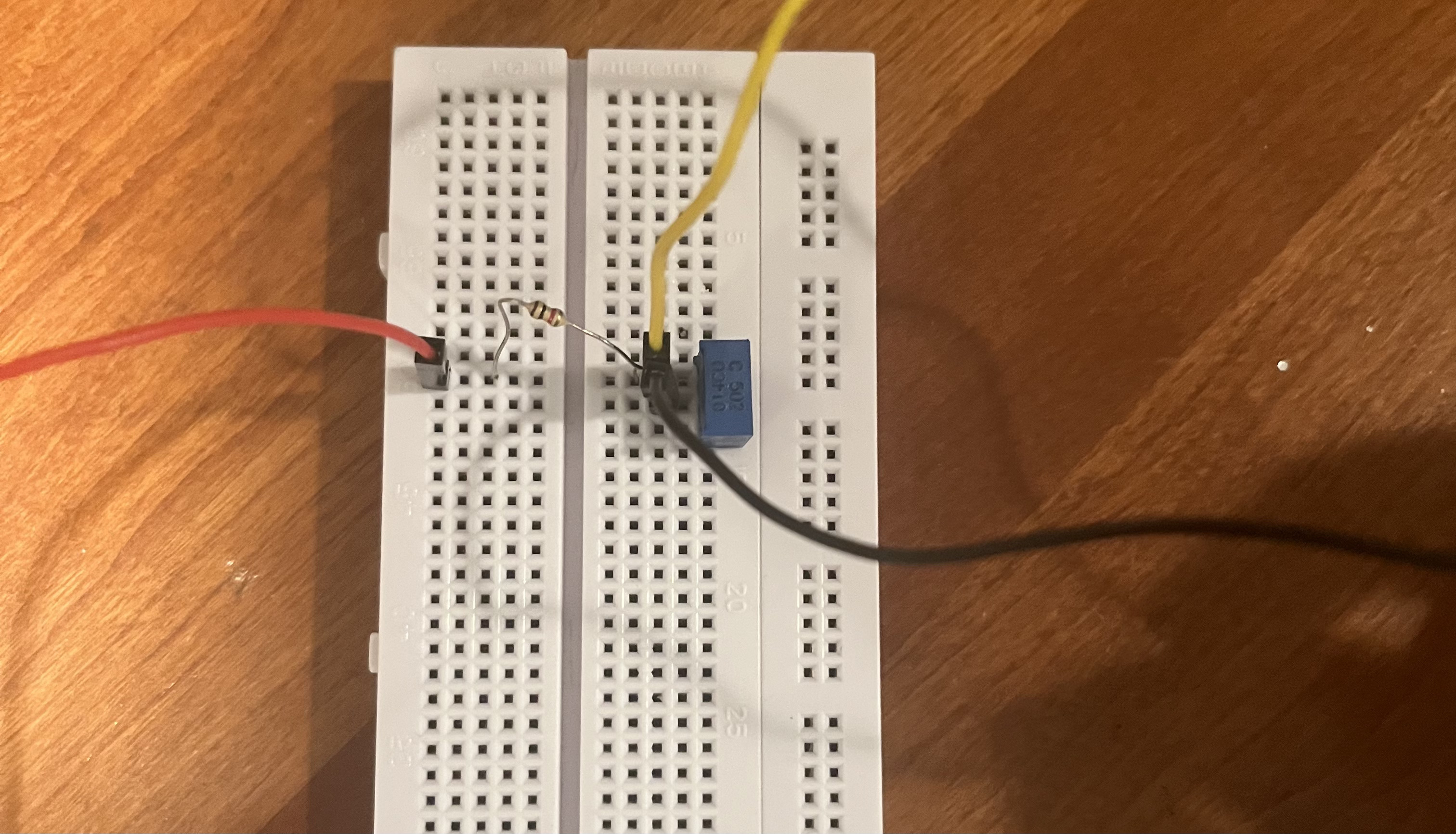
This ciruit is used to convert a 2000 V input into a controllable 0-10 volt output for safe use with an arduino.
Components
1M Resistor, 5k Potentiometer
Wiring
- Place 1M Resistor in series with voltage source
- Place 5k Potentiometer in series with 1M Resistor
- Connect arduino to node connecting resistor and potentiometer
Schematic
Physical Circuit
Voltmeter (old)
Warning
This component is no longer used in the design; it is deprecated in favor of the voltage sensor circuit.
Overview
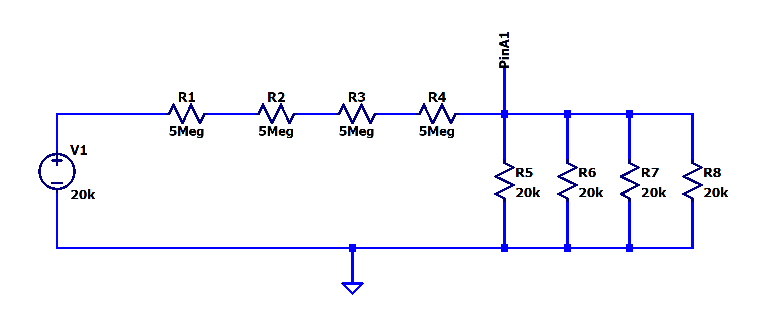
The circuit configuration below is a voltage divider supplied by a 20V voltage source. The voltmeter will send a analog signal to the Arduino through a wired connection. To prevent short circuiting, place the voltmeter wire in parallel with the voltage divider. This circuit does not use any active components.
Components
- 5Meg Ohm Resistors (4X)
- 20K Ohm Resistors (4X)
- 20V Voltage Supply
Wiring
- Connect all four 5Meg ohm resistors in series
- Connect all four 20k ohm resistors in parallel
- The 5Meg resistors and 20k resistors should share a node, then connect the parallel branches of the 20k resistors to Arduino GND
- Place the 20V voltage supply to the series 5Meg resistors and to GND
Schematic
Physical Circuit
An image of the physical voltmeter circuit is not yet available, but will be added once constructed and tested.
LED Signal
Overview
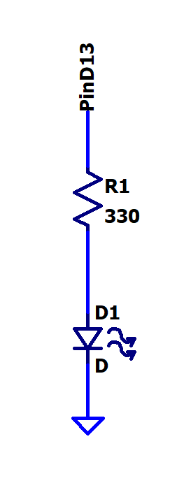
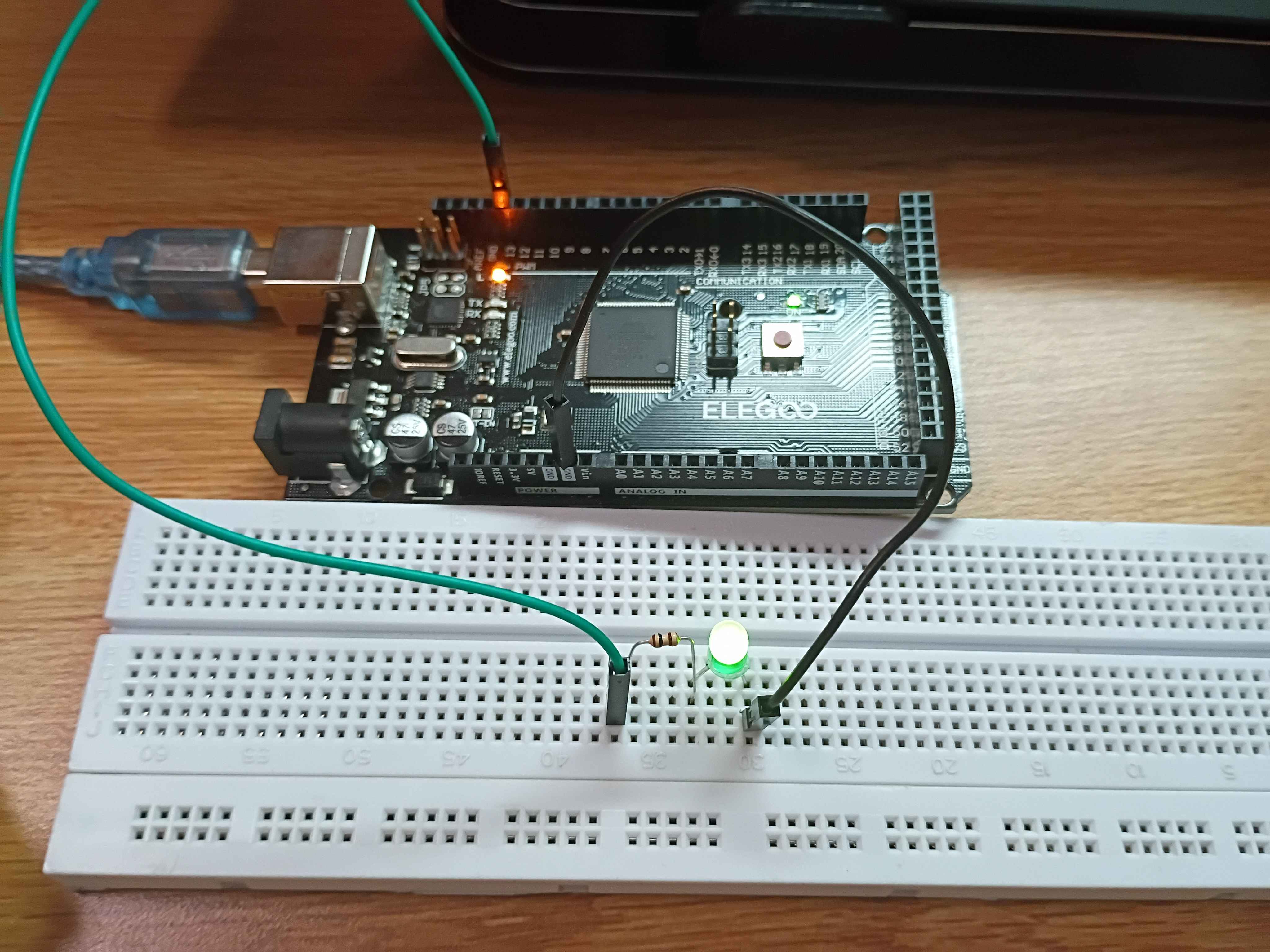
This circuit uses an LED to signal operational status of the full sensor circuit. The resistor and LED are connected to the Arduino.
Components
- 330 Ohm Resistor
- LED
Wiring
- Connect the resistor to Arduino Pin D13
- Connect the 330 resistor in series with the LED (Long leg of LED should be connected to the voltage supply side)
- Connect the other end of the LED to Arduino GND
Schematic
Physical Circuit
Electron Beam (Enable)
Overview
The ZVN3310A is a low power N-channel MOSFET for voltage controlled switching. It has a 300V max voltage & 450mA max current, and has a gate threshold voltage of 2.4V. It uses a 3 pin configuration with drain, gate, and source. The MOSFET is used to turn the ciruit on/off to enable the electron beam. Note: BSP89 is discontinued.
Components
- ZVN3310A N-channel MOSFET
- 10k Ohm Resistor
Wiring
- Connect Gate to Arduino Pin D8, and a 10k pull down resistor to ground on the same node
- Connect Source to Arduino GND
- Connect Drain to a negative voltage source
Schematic
%20LTspice.png)
Physical Circuit
.jpg)
Electron Beam (PWM)
Overview
The ZVN3310A N-channel MOSFET will also be used for the electron beam PWM circuit. The MOSFET is switch the circuit on/off rapidly to adjust the electron beam strength using pulse width modulation. The 3.3V or 5V PWM signal will be applied to the gate to modulate the duty cycle to product variable power. Note: BSP89 is discontinued.
Components
- ZVN3310A N-channel MOSFET
- 10k Ohm Resistor
- 100 Ohm Resistor
Wiring
- Connect Gate to Arduino Pin D8, and a 10k pull down resistor to ground on the same node
- Connect a 100 gate resistor in between the Arduino Pin D8 and the MOSFET gate to prevent current spikes
- Connect Source to Arduino GND
- Connect Drain to a negative voltage source
Note
If the electron beam has a inductive load (motor / relay) for switching, add a flyback diode to stop back EMF. A Heatsink may be helpful for the MOSFET at high temperatures.
Schematic
%20LTspice.png)
Physical Circuit
.jpg)